

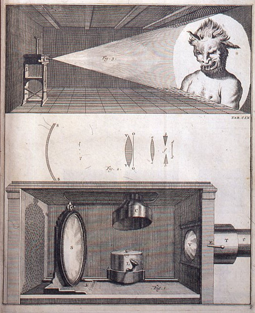
Magic Lantern of Jan van Musschenbroek as depicted in “Physices Elementa Mathematica,” 1720
ANCIENT PROJECTIONISTS
Early projection arts relied on natural light and fire. We don’t know for certain at what point early humans learned how to make the shadow of their hand resemble a dog, or a bunny, or a bird, but we do know that scientists in the early days of recorded history already had a sophisticated understanding of the physics of light. The Han Chinese Philosopher Mozi and the Greek Philosopher Euclid both described the phenomenon of light passing through a small aperture and projecting an upside-down image on the other side, which would eventually become known as the Camera Obscura.
If you have ever made a pinhole camera, you have made a Camera Obscura. From the Latin for “dark room,” the concept was employed throughout the world in a variety of novel ways, but until the advancements in optical mirrors and lenses of the 17th century, its potential as a projection tool was limited. The flipped image it produced, however, demonstrated that light travels in a straight line.
DIAPHANOUS MIRRORS AND PUPPETS
The development of reflective technology was already well underway more than 2000 years ago in China’s Han Dynasty. Skilled metalworkers created intricate brass “light penetration mirrors,” often known in the west as a Chinese Magic Mirror. These little wonders featured intricate patterns and motifs on one side, with tiny imperfections introduced to the flat metal surface on the back. When reflecting light off of the slightly concave mirror side, the decorative pattern on the opposite side is projected seemingly from nothing.
Around the same time in the 1st Millennium BCE, the development of Shadow Play theater performances took off in Asia. Performers told stories by casting their shadows on a back-lit cloth stage. Diaphanous puppets made of cloth and leather emerged to cast an ethereal presence onto the stage. Many cultures in Asia still practice their own versions of this early projection art with the addition of modern lighting.
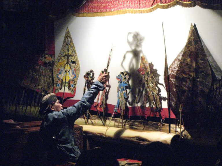
A modern Wayang Kulit performance
While the craft was firmly rooted in Asia, it eventually spread westward, reaching the Middle East in the 13th or 14th century CE, and then to Europe with French missionaries returning from China in the late 17th century CE. While these Ombres Chinoises, or Chinese Shadows, did have a cultural impact in the west, post-renaissance Europe was in a scientific fervor, and they faced stiff competition from an emerging technology that would soon become the preeminent means of projection for the next few centuries:
THE MAGIC LANTERN
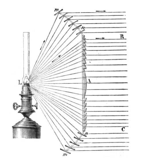
The Magic Lantern, widely credited to Dutch scientist Christiaan Huygens in 1659, was built upon the principles of the Camera Obscura and a century and a half’s worth of experiments with new optical technology. Leonardo Da Vinci drew a similar projection device in 1515, and other inquisitive minds began combining lenses and mirrors to create all manner of microscopes, telescopes, and optical illusions, although none of them were widely available to the public. When the Magic Lantern debuted, candles and oil lamps were still the only artificial light sources available, but the improvement of concave mirrors and condenser lenses allowed for those light sources to be concentrated into a beam intense enough to project images at previously unseen distances.
Those images first came in the form of hand-painted glass plates that a lanternist would slide into a slot just at the point where the controlled light beam converged into focus, but the medium expanded rapidly to enable all manner of enchanting illusions. These slides were sandwiched between two pieces of wood and could be made with multiple image layers, which let a lanternist create movement within a projection by manipulating a small lever, thereby moving the layers independently. Stacking two or three Magic Lanterns allowed for even more layering and movement, as well as transitions like dissolves.
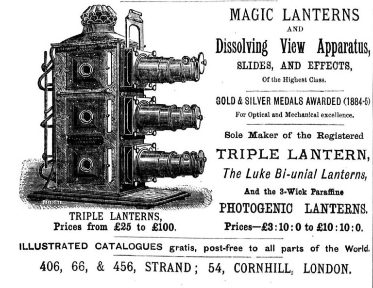
Advertisement for Triple Lantern, 1886
The introduction of mechanical gears inside the slide itself enabled colorful abstractions like the Victorian Chromatrope, which used a small crank handle to rotate two discs with colorful patterns in opposite directions and create a dynamic color spectacle, much like a kaleidoscope.
NATURAL PHILOSOPHY AND OPTICS
New optical technology wasn’t just accelerating humans’ ability to create a spectacle, it was advancing our knowledge of the inner workings of the universe. New glass-making techniques using lead resulted in optically clear, low-dispersion lenses and prisms. More than just the inventor of one of the most popular projection systems of all time, Christaan Huygens was a Natural Philosopher who, with his 17th-century contemporaries, sought to explain the inner workings of the world. Huygens and others observed the reflections, diffractions, and refractions of light and proposed that light was a wave, a luminiferous ether that spread out from its source in all directions.
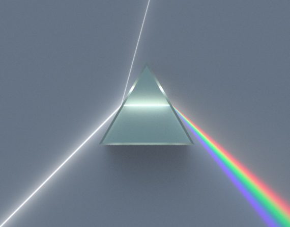
A prism splitting white light into distinct color wavelengths.
Famed English Physicist Isaac Newton disagreed, believing that if light traveled in a straight line, then it could not be a wave. Newton observed the way a prism of glass separated a beam of light into a distinct spectrum of colors and concluded that this separation could only occur if light was made of incredibly tiny particles, or corpuscules. The two opposing schools of thought went back and forth for centuries, but the mystery persisted.
Newton’s experiments with prisms also demonstrated one of the inherent challenges of producing a clear optical image with glass lenses, chromatic aberration. Since the color separation that occurred with the glass optics of his telescope interfered with his astronomical experiments, he constructed a telescope made of mirrors instead. This, in turn, inspired Swiss Astronomer Leonhard Euler’s Episcope in the mid-18th century. It is also known as an opaque projector because instead of focusing a beam of light through a translucent medium, it illuminated the surface on which it sat. A hole in the bottom meant the episcope could be placed over any image or object, then a mirror at the top would reflect the image of that object through a lens to create an enlarged, albeit dim projection.
THE PERSISTENCE OF VISION
By the 19th century, Magic Lantern shows were nearly ubiquitous, and the Industrial Revolution was in full swing. The invention of the Argand Lamp in 1780 and the limelight in 1826 made Magic Lanterns and episcopes brighter than ever before. The advent of controlled electrical lighting like the Carbon Arc lamp and incandescent bulbs were an even bigger improvement as the infrastructure to power them expanded. An enormous increase in the pace of research and development in the fields of chemistry, physics, electricity, magnetism, engineering, and countless others in the 1800s gave birth to an explosion of scientific and technological advancements that would lead to the advent of projected cinema before the century’s end.
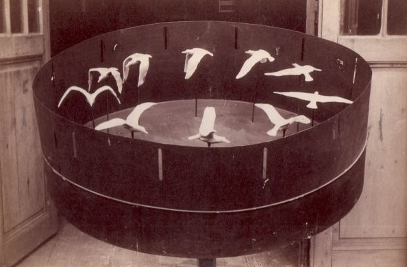
Étienne-Jules Marey’s zoetropes used sculpted sequences instead of planar images, 1887
Early experiments in animation like the Phenakistiscope in 1833 demonstrated the phenomenon of persistence of vision, which allows the human brain to perceive small incremental differences between images as a sequential movement. Where the Phenakistiscope was a flat disc that showed every stage of a painted sequence at once as it rotated at speed, its near-immediate successor, the Zoetrope, put the image sequence on the inside wall of the spinning cylinder and was viewed through a narrow vertical slit in the cylinder wall to create enough separation between each individual part of the sequence to fools the eye into seeing continuous motion. These early painted animations were not projected, but they laid the groundwork for innovations to come.
SEQUENTIAL MOTION IN LIGHT
Photographers in the late 19th century, most notably Eadweard Muybridge, were capturing sequential motion in the form of Chronophotography but had no means of projecting those sequences at speed, though Muybridge did show Chronophotographic sequences frame by frame with a Magic Lantern. To be projected at speeds sufficient to maintain persistence of vision required Muybridge’s Zoopraxiscope, which placed a photographed sequence on a thin paper or glass disc which then rotated between a lamp and a lens to project rapidly advancing moving images.
In the late 1880s, French lantern slide painter and inventor Émile Reynaud replaced the rotating mirrors of his similar Praxinoscope with a light source and attached a reel of hundreds of hand-painted gelatin plates mounted in a cardboard strip that advanced via a turning handle. In 1892 his Pantomimes Lumineuses debuted in Paris. The projections of this Theatre Optique had much longer movement sequences than a Magic Lantern show. Still, the interval between motions was not short enough to appear persistent, and the gelatin and cardboard medium was not very durable under the strain of constant exhibition. Reynaud exhibited this show to half a million people over 8 years but had to laboriously repaint entire sequences to keep it going.
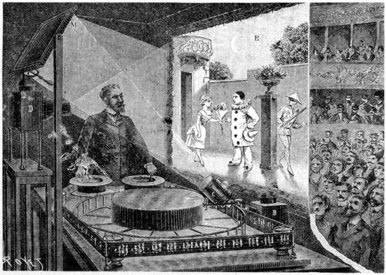
Émile Reynaud’s Theatre Optique
CELLULOID AND MECHANICAL PHOTOGRAPHY
While Reynaud was painting on gelatin, experiments with photographing and projecting sequences on rolls of paper film also demonstrated the need for more durable materials, and by 1889 the Eastman Kodak company had introduced plastic Celluloid Film. Within two years, Thomas Edison’s team of researchers, led by William Dickson, had cut the 70mm celluloid strips in half and added perforations, known as sprocket holes, to create the first viable 35mm motion picture film stock.
Dickson’s team rapidly adapted clockwork mechanisms to create the Kinetograph motion picture camera and its companion viewing device, the Kinetoscope. Producing the illusion of smooth motion on film required the ability to advance the film frame by frame and stop the film in place long enough to expose each frame without blurring the image. The addition of a round shutter rotating in sync with the film’s advance blocked the light from hitting the film as it moved to the next frame. For the illusion to work, this had to happen at least 16 times every second with every part of the mechanism working in concert. The half-ton, battery-powered Kinetograph captured 40 frames every second.
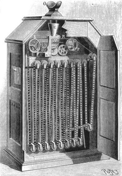
Interior view of Edison’s Kinetoscope
To display these images required the same intricate mechanical harmony. The Kinetoscope was the first machine to display moving cinema images, but it was not a projector – only one person at a time could view these movies by looking through a small viewport. In Paris in 1894, one of those viewers was Antoine Lumière, who, along with his brother Louis, had just recently taken over their father’s photography business. The Lumière Brothers determined to make an even better machine, and at the end of 1895, they hosted the first public screening of projected motion film with their own invention, the Cinématographe.
THE BIRTH OF CINEMA
The Lumière brothers modified the mechanism of a sewing machine to achieve intermittent motion, and instead of electricity, they relied on a simple hand crank. While this only allowed them to shoot and project 16 frames per second to Edison’s 40 frames, the result was a much lighter, portable device that could not only shoot films but also project them with limelight. While Edison’s heavy Kinetograph was immobilized in a dark studio in New Jersey, the Lumières’ all-in-one Cinématographe was being replicated and sent around the globe, with operators shooting and screening movies worldwide.
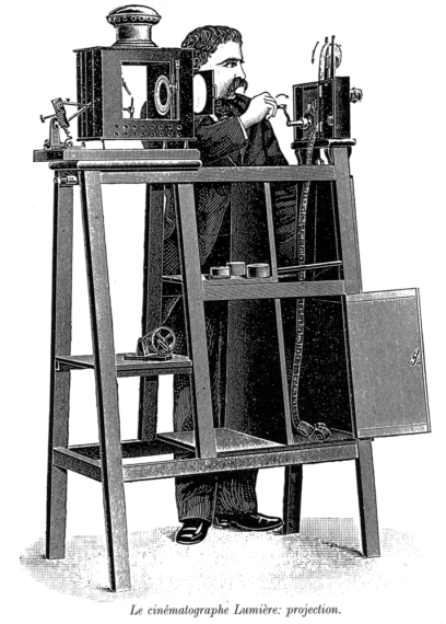
Cinématographe configured for projection
The technology that powered the Cinématographe has been tweaked and refined, but the basic mechanism in film projectors and cameras remains relatively unchanged even today. The Lumières, however, did not see a future for their invention, and gradually focused most of their attention on developing color film processes, leaving other filmmakers and inventors to fill the void.
The first decade of cinema was largely a traveling roadshow, with screenings moving from one temporary venue to another, but by 1905 the first permanent movie theater, “The Nickelodeon” was established in Pittsburgh, Pennsylvania. Access to the electrical grid meant that projectors could use more consistent incandescent lamps and more powerful carbon-arc lights. The 2-in-1 Projector and Camera combination became less relevant, and Film Studios began to build their own movie theaters exclusively to screen their respective productions.
EARLY FILM GAUGES AND CONFLAGRATIONS
Film Projectors and Cameras were produced in a huge variety of formats, all vying for preeminence. The differences in film gauge (or width), and the size, spacing, and location of the perforations that allow the film to advance led to compatibility and distribution issues between standards, and within a few decades most projectors and cameras were using the same formats. The larger film gauges, like 70mm and 35mm, were akin to today’s 4k UHD and 1080 HD formats in picture quality, but because the film was physically bigger, it was more expensive to produce, shoot and store compared to smaller gauges like 16mm and 8mm, which were similar to SD and VGA resolutions and more frequently used in schools, homes and other smaller venues. These gauges are related by a factor of 2 because they were created by cutting a larger film strip in half down its entire length.
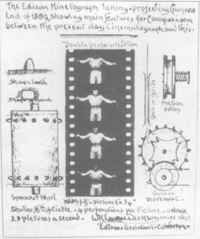
Dickson’s 35mm Film Standard
If the film jammed while running through the projector, it would often burn in place from the intense heat of the lamp behind it. Kodak’s first Celluloid film was made of Cellulose Nitrate, which was also used as gunpowder due to its extreme volatility. Fires in projection booths and storage areas were a very real danger, and nitrate film’s flammability only increased with age. By 1909 Nitrate began to be replaced by more stable Celluloid Acetate film stocks, although it remained in use into the 1950s. Since the 1980s, Polyester has been used as the base layer for photographic film.
THE CHEMISTRY BEHIND THE SILVER SCREEN
The plastic base layer of a filmstrip functions to hold an emulsion of light-sensitive chemicals that react when exposed to light. Most photographic emulsions have been composed of silver halide compounds. Silver nitrate, silver chloride, and their photoreactive properties were discovered hundreds of years before the first successful photograph was permanently “fixed” by chemically stabilizing the light-sensitive reaction. Individual grains of the silver emulsion react by darkening depending on how much light they are exposed to, and then a chemical wash halts the process and removes the grains that have not reacted, leaving behind a negative black and white image made of millions of individual crystals.
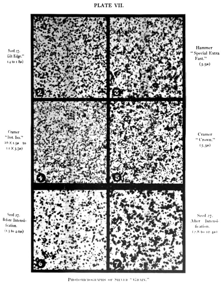
close-up view of the grain structure of black and white photographic emulsion
Photographic Enlargers projected the negative image onto a sheet of photosensitive paper, which was then developed and chemically stabilized to produce a final positive photographic print. In the 1920s the Optical Printer applied the same concept to transferring images between strips of motion picture film by pairing a film projector and a film camera together in mechanical sync, which enabled the complex masking and compositing of multiple layers of moving images. It was used for special effects and some animation techniques and remained an important tool into the late 20th century.
SPECIAL EFFECTS AND ASTRAL ILLUSIONS
Optical printing was not the only option for creating special effects, using projectors on film sets in rear projection and front screen projection setups were also common techniques to combine scenes into one final image. A previously filmed background scene would be projected onto a large screen from behind the stage, while to a camera on the other side of the screen, actors appeared to inhabit fantastical worlds and noisy situations where trying to record dialogue would otherwise prove fruitless. Projectors were also a popular practical lighting effect, displaying images directly onto the scenes or actors on camera.
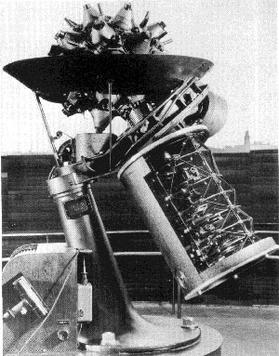
Zeiss Mark I Planetarium Projector, 1926
Other purely mechanical optical illusions emerged. On one end of the spectrum, the incredibly complex Zeiss Planetarium projectors could recreate the movements of the stars through the night sky on the inside of a large dome. On the other end of the spectrum, a GOBO disc inserted into a spotlight assembly could create patterns and images for theatrical performance, as well as film lighting effects, mimicking rain, trees, and window frames, or summoning vigilantes. Adding plastic color gels to the GOBO gave it even more flexibility.
COLOR FILM AND THE ELECTROMAGNETIC SPECTRUM
Adding color to film projection proved more difficult. After nearly a century of research and development by photographic pioneers, the addition of red, green, and blue chemical dye layers on top of the silver emulsion led to the emergence of the first viable forms of color photography in the 1930s, and Hollywood’s 1939 The Wizard of Oz dazzled theater-goers with the first moving color film images. This technique built upon the Young-Helmholz Trichromatic Color Theory suggested more than a century prior. Helmholtz and Young postulated that the average human eye receives primary colors via three separate types of light-sensitive cells, and then the brain combines each cell’s information into what we perceive as full color.
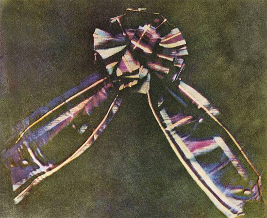
The world’s first color photograph by Physicist James Clerk Maxwell
This theory inspired Scottish scientist James Clerk Maxwell to produce the very first color photograph in 1861. Four years later, Maxwell went on to revolutionize our understanding of the universe with his Dynamical Theory of the Electromagnetic Field. Maxwell observed that magnetic and electric fields both traveled in waves at the same constant speed as light does. Since these waves move at a constant velocity, different levels of energy manifest as variations in the frequency at which those waves oscillate. Together, the range of energy levels of these radiation waves is known as the Electromagnetic Spectrum.
ELECTROMAGNETIC RADIATION AND THE HUMAN EYE
Most of these waves are not visible to humans. Low-frequency radio waves, microwaves, and infrared waves have the longest wavelengths, and high-frequency ultra-violet, x-rays, and gamma rays have the shortest wavelengths. Between these two ends of the spectrum is a tiny range of electromagnetic radiation frequencies that we know as visible light. These frequencies stimulate the three unique types of light-sensitive cells in your retina, which we know as cone cells.
Each of the three kinds of cone cells in the human retina are sensitive to a specific range of the electromagnetic spectrum. When a specific frequency of radiation hits one of these cone cells, that sends a signal to the brain, which interprets it as what we know as red. A different frequency wave hitting a cone cell sensitive to that range tells the brain it has seen blue, and a third cone cell communicates when it comes into contact with green wavelengths of electromagnetic radiation.
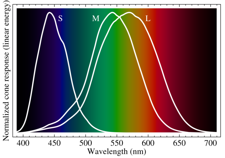
The sensitivity range of the three types of human cone cells to the visible wavelengths of the electromagnetic spectrum.
These distinct color signals are interpreted in the brain as a sum of their parts, like mixing different colors of paint together. Applying this same additive color strategy to photographic film with different layers of color dyes successfully replicated this phenomenon. Modern photographic film stocks, as well as ink printers, tend to use CMYK subtractive color – in which Cyan, Magenta, and Yellow are removed from White light to render colors, but electronic display systems use the additive RGB color space.
Many of these early color films were positive images, which meant that they could be viewed directly without the need to print them with a photo enlarger. While Magic Lanterns were still used to project glass photographic slides well into the 20th century, the new 35mm photographic slide film projectors that became popular in the 1950s and ‘60s finally relegated the Magic Lantern to obsolescence and became a feature of classrooms, conference rooms, and homes.
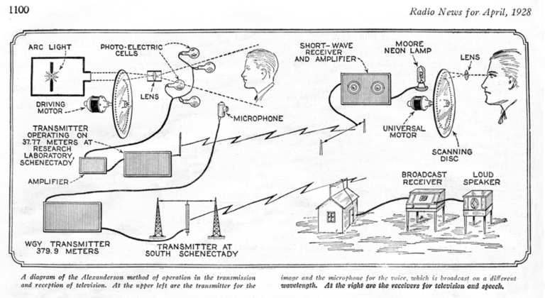
MECHANICAL TELEVISION AND THE RASTER SCAN
The 1950s also saw the advent of commercial television. While not all televisions are strictly projectors, the television’s technological advancements in transmitting, receiving, and rendering electrical and radio signals into a moving image are also the foundation of digital projection. In 1884 German inventor Paul Nipkow patented his eponymous Nipkow Disc, a simple wheel with a spiral pattern of aperture holes. When combined with newly invented photovoltaic sensors that could convert light into electrical signals, scientists were able to electronically transmit and display simple images with light by 1885. As the disc rotated over a thousand times per minute in front of a light sensor, the variations in brightness as each moving point of light passed by were converted into an electric signal, with each hole in the spiral forming one vertical line of the frame from left to right. This technique was known as raster scanning.
The mechanical television we could have had.
Scotsman John Logie Baird experiments with displaying these raster scans by synchronizing a second Nipkow disc and using the encoded light signal to modulate the voltage of a neon lamp behind the viewing disc were known as the mechanical televisor. The image was tiny, particularly compared to the size of the machine itself, and was very high contrast, but it demonstrated an alternative to chemical film. Instead of rendering each individual frame of an image sequence in its entirety for a fraction of a second like a film system, mechanical television leveraged persistence of vision and the raster scan to record and display just a small portion of the image frame for an even smaller increment of time. The rapidly changing brightness, synchronized with the spiraling movement of the disc holes, caused the raster scan to appear as one continuous image – though in reality, it was recreating an image point by point, faster than the human eye could perceive.
CATHODE-RAYS AND THE ELECTRON
The loud, cumbersome mechanical viewing device was quickly surpassed by a more elegant electronic solution, the Cathode-Ray Tube. Much like chemical film, the CRT was the result of centuries of research and advances in manufacturing capabilities. 19th century Scientists created vacuum tubes with positive and negative electrodes on either end and observed how the slowed passage of electrical charges through xenon and neon created a fluorescent glow as a mysterious force collided with the gas inside. In the late 19th century, vacuum tube manufacturing techniques were able to create an atmospheric pressure low enough for scientists to observe a new phenomenon. As more and more gas was pumped from the vacuum tube, the glow moved further and further away from the negatively charged cathode, and in a total vacuum, the tube itself began to glow at the positively-charged anode at the opposite end.
The observation of these cathode-rays was the genesis not just of electronic imaging, but a more concrete understanding of atomic physics. For centuries, humans had experimented with electricity without fully comprehending the forces they were harnessing. By the mid-1800s, scientists were relatively confident that everything in the universe was made of miniscule molecules and even tinier atoms. In 1897 British Physicist J.J. Thompson successfully measured the mass of a cathode-ray inside a vacuum tube and found that it was 1000 times smaller than that of a hydrogen atom. He concluded that the cathode-ray was made of negatively charged “corpuscules,” although that name was quickly replaced by the one used today, the Electron.
ELECTRON BEAMS AND PHOSPHOR SCREENS
Thompson’s research built on the work of James Clerk Maxwell and his notable 19th century colleagues, Carl Friedrich Gauss and Michael Faraday, whose theories of electromagnetic radiation inspired Thompson to go on to use a magnetic field to divert the path of his cathode-ray. This critical experiment gave us not only a deeper understanding of the building blocks of our universe but also television.
When electrons are shed from a negatively charged cathode and travel towards a positively charged anode in the vacuum of a cathode-ray tube, there are no gas atoms for them to crash into, so they travel in a straight unobstructed line known as an electron beam. By adding a phosphorescent material on the positively charged side of the vacuum tube and moderating the electrical voltage, researchers were able to accurately control the brightness of the point of light that occurred when the beam of electrons collided with the phosphor coating. An electromagnet placed around the cathode could divert the electron beam to anywhere on the phosphor surface with an electrical signal.
EINSTEIN AND THE PHOTON
8 years after Thompson discovered the electron, Albert Einstein unified Newton’s particle theory with Huygen’s and Maxwell’s wave theory, determining that the waves of the electromagnetic spectrum were made up of discrete particles of energy which are released and absorbed as electrons change energy states and move between atomic orbit levels, like when a beam of electrons collides with a phosphor screen or a hydrogen molecule. This small elementary particle is the force carrier not just for the light that comprises our visible world, but for the quantum mechanical function of the universe. This corpuscular unit of energy’s existence was proven through skeptical experimentation and given the name Photon in 1926.
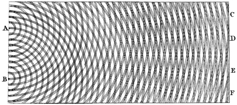
Thomas Young’s double-slit experiment demonstrated the diffraction of light waves after passing through an aperture.
That same year, Japanese High School Teacher Kenjiro Takayanagi used a cathode-ray Tube to display a static image recorded by a Nipkow Disc raster scan. By rapidly changing an electromagnetic field to direct a sub-atomic beam of electrons onto a reactive phosphor surface thousands of times a second to create photons that combine to form an image, Takayanagi achieved the first electronic illusion of persistent vision in 40 lines of point-by-point resolution. Other systems debuted by Philo Farnsworth and Vladimir Zworykin shortly afterward used electronic technology to capture a raster scan instead of a mechanical Nipkow Disc, but it would be decades before the CRT Television became commercially available in the 1950s.
ELECTRONIC PROJECTION AND EXPERIMENTAL FILM
The concept of using a CRT as a display was also applied to optical projection. With the addition of a lens in front of a small bright CRT, the image could be thrown through space and displayed on any surface, instead of on just a small screen. In fact, limitations in the size of phosphor screens in early CRT televisions meant that most early TV units were projection televisions, which used a lens to throw an enlarged CRT image onto a rear projection screen instead of viewing the phosphor of the CRT directly. This style of projected television screen was a popular alternative through the end of the 20th century until its eventual replacement by LCD and DLP projectors. Color CRT projectors debuted in the 1950s but were not commonly found for a few more decades. Using three CRTs together, each with their own lens, to project individual RGB channels simultaneously, they could accurately project accurate colors images without loud moving parts or film strips.
The introduction of commercial television inspired some filmmakers to experiment with new ways of projecting images without creating persistent vision. Stan Brakhage and others made films without a camera, by manipulating the film strip physically, whether by taping insects and flora to it, scratching off layers of emulsion, or painting it. Their creations, when run through a film projector, did not show a sequence of images but rather thousands of subtly-related individual abstract frames.
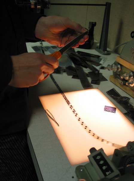
The author adhering 35mm slides to 16mm clear leader.
IMMERSIVE PROJECTION EXPERIENCES
CRT projectors were not bright enough to replace film projectors in most situations, but the situations and ways in which projectors were used continued to grow. In 1969, Disneyland’s Haunted Mansion became the first projection mapping experience. Using 16mm footage of ghostly faces on a black mat background to selectively illuminate a physical counterpart in space, it created an ethereal illusion that had never been seen before. Projection elements have been a part of amusement park rides ever since.
IMAX projection, developed in the 1960s, also immersed its audience by covering as large an area as possible with light. The IMAX format turned the image frame sideways and ran its 70mm film horizontally to maximize the picture. The gigantic projector emerged from the floor in the middle of a large dome, much like a planetarium, and an ultra-wide lens threw the image onto every part of the enormous curved surface. The audience seated below saw an illuminated image that filled nearly their entire field of view, and the movement at the periphery of their vision made for one of the most thrilling projection experiences yet.
A much less bulky projection system was also being used to create immersive experiences of an entirely different sort. The overhead projector developed by the US military in WWII used a mirror and condenser lens to project translucent images that are placed on top of a backlit Fresnel lens. The Fresnel lens, invented by the French physicist of the same name, uses concentric rings to gather a light source into a concentrated beam. Since 1827, the bulky glass versions have been used in lighthouses and high-powered searchlights. A smaller, thinner, rectangular version was developed as a screen for CRT projection televisions, and the same materials soon became a surface for live-projected content creation. Images and documents could be printed onto transparent plastic sheets, but they could also be written on directly.
Collimating light with a Fresnel lens
LIQUID LIGHT AND LASER SHOWS
This useful tool became common in schools and meeting rooms, but it also unlocked a new art form for people looking for a less structured experience. Liquid Light Shows were popular additions to Psychedelic Rock shows, as groups of artists began to project the interactions of oil, water, alcohol, and colored dyes onto a performance stage. These shows grew to use multiple overhead projectors, slide projectors, and film projectors, some with spinning color wheels placed in front of the beam. In some cases, multiple people operated over a dozen different projectors all at once, layering abstract and realistic imagery on top of each other.
The addition of luminous abstract images as a visual accompaniment to musical performances led to the development of Laser Shows shortly afterward. Laboratory experiments in the late ‘50s and ‘60s produced the laser, which could emit specific wavelengths of visible light in a narrow concentrated beam without diffracting. By using a galvanometer scanner to rapidly change the direction of the laser beam, a laser light show could act like the electron beam in a CRT and project a scan across the sky to the delight of crowds below.
Like a CRT, the first laser light shows used an analog electric signal, the position of each point of the raster scan at any given moment was encoded as a wavelength which was read by a receiver, then used to control the direction and intensity of the beam to recreate an image dot by dot. The advent of computers, silicon microprocessors, and new storage media ushered in a new way of encoding signals and information digitally by turning a wave signal into a series of numbers, which could be stored more reliably, and then turned back into a voltage wave when needed.
LIQUID CRYSTAL DISPLAYS
Decades of laboratory research and the miniaturization of electronic components yielded new ways of displaying imagery digitally. Liquid Crystal Displays treat each point of an image as a discrete unit, or pixel, represented by an individual Liquid Crystal with its own pair of attached electrodes. By applying electricity to a liquid crystal, the polarization of the crystal is altered to adjust how much light passes through to the other side. By arranging these LCDs in a rectangular grid matrix and controlling the intensity of each LCD pixel individually, a full translucent image can be formed. Since LCDs only control the amount of light transmitted through them, they require additional illumination and colorization.
The first working LCD projector prototypes appeared in 1971, but LCDs with a high enough resolution to display video didn’t arrive until the late 1980s. Unlike the backlit LCD screen, LCD projectors employ three separate small LCD panels, and a series of dichroic mirrors which split a white lamp beam into red, green, and blue channels. The mirrors direct each color channel through its dedicated LCD, and then through a prism to recombine the RGB channels back into one aligned beam of full-color video. Unlike film projectors and CRT displays, when powered, LCDs are always on, a constantly shifting translucent image. They maintain persistent vision by refreshing the opacity value of each pixel, line by line, dozens of times per second.
DIGITAL LIGHT PROCESSING
The LCD wasn’t the only technology being developed as a digital alternative. Texas Instruments’ Digital Light Processing Chip took a different approach by selectively reflecting light with a Digital Micro-Mirror Device to create a projected image. Instead of transparent crystals controlling the intensity of each pixel, thousands of tiny addressable mirrors arrayed on a DMD moved rapidly between an on and off position to reflect the light beam either into, or away from the front lens of the projector. A spinning color wheel placed between the beam and the DMD separated the light into color channels, so the micro-mirrors rapid switching occurred multiple times for every full refresh of the image, with each tiny mirror staying on or off for a different amount of time for each color channel depending on the brightness needed to mix the color properly.
The pulsing colors of the 1DLP chip color wheel meant that they never fully combined into a single beam like a CRT or LCD projector, and were not able to reproduce as many colors. The improved 3-chip DLP configuration fixed that issue by splitting the light beam into red, green, and blue channels with a prism, and directing each color beam towards it’s own dedicated DMD, which in turn reflected their respective color channel towards another prism to recombine them again into a full color projection.
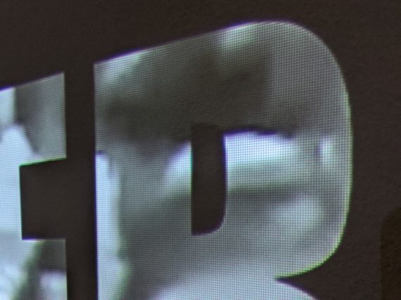
The pixel grid of a 3LCD Epson 1060.
LASER AND LED LUMINARIES
Both 3LCD and 3DLP projectors have used a variety of different types of lamps to illuminate the images they render on their chips, but in recent years white light sources paired with color-splitting optics are being replaced by Lasers and Light Emitting Diodes. These advanced modern luminaries emit red, green, and blue light as individual channels, with each beam directed to its own dedicated LCD or DLP micro-mirror array before combining it to a full-color image. These discrete RGB light sources are not just more efficient than a traditional lamp; they also produce a wider range of color combinations, to project even richer, more vibrant images.
Digital projectors have improved not just in brightness and efficiency, but in resolution, adding more pixels to increasingly smaller LCD and DMD arrays. Small handheld LED projectors can turn any surface into a movie screen and then fit in a pocket. Larger digital projectors have mostly replaced their film counterparts, displaying large crisp 4k and even 8k images without the need to store and maintain large film reels. They also bring some advantages that increase their resolution further. Software programs stack and blend multiple projectors together to create one enormous image, covering the exterior of an entire building, or transforming the interior into one seamless projected surface.
COMPUTERS AND THE FUTURE OF PROJECTION
Other advancements in computing have also made projection mapping a much simpler process than Walt Disney’s 16mm celluloid ghosts. Masking and compositing objects to selectively illuminate objects in space no longer requires optically printing film frame by frame, a digital video can be created, modified, and displayed in real time. A process known as visible structured light scanning, a digital projection of black and white patterns recorded by a camera, is used for measuring 3D scenes and objects in a variety of industries. This technique makes video mapping even easier. Software algorithms determine the position where every pixel of the projector hits the scene, meaning you can create a projected video map over a color and depth image of the scene in front of you, aligning projected images with complex objects in space is now a simple operation.
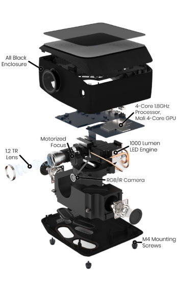
Exploded view of a Lightform LF2 augmented reality projector.
HISTORY OF PROJECTION – STANDING ON THE SHOULDERS OF GIANTS
The widespread popularity of projection today can make it easy to take the intricacies of this advanced technology for granted. Understanding just how a luminous image is made doesn’t lessen the magic of the experience; in fact, it can increase your sense of wonder and appreciation for the tools our ancestors made. At Lightform we are not only closely tracking developments in projection technology, but also working hard to further the creative potential of projection tools to enable you to create magic with light.
~ Sean Servis
Note:
As of August 12th, 2022, Lightform is no longer in business and is no longer providing technical support for the product. Please refer to the Lightform Guide and FAQ for self-help resources.
